


Built-in support for the SAE J1939 CAN bus standard opens exciting new possibilities for the integration of electromechanical actuators into agricultural, construction and mobile off-highway applications
By Chad Carlberg
Product Line Manager for Linear Actuators
Thomson Linear
www.thomsonlinear.com Thomson@thomsonlinear.com
Where traditional electric linear actuators have provided the most basic machine functionality -- pushing or pulling a component on command via a switch -- the increasing integration of advanced electronics is making today’s actuators safer, smarter and easier to network with agricultural, construction and mobile off-highway equipment. Modern linear actuators track critical parameters remotely and react to them automatically. They deliver inexpensively real-time operating status and network flexibility with other systems. All of this is the result of incorporating a programmable microprocessor to meet market demand for greater safety, functionality and modularity.
Condition monitoring for safe operation
In a conventional electric actuator design, continuous overloading can damage the motor and other components. An actuator that fails at the wrong time could damage equipment or present a safety hazard, especially in heavy duty agricultural, construction and mobile off-highway applications.
Onboard electronics prevents such incidents by monitoring current, voltage, load and temperature, and shutting down the system safely if it exceeds critical set points. For example, if the recorded temperature is higher than that for which the actuator is rated, the electronics will guide the system to a safe shutdown.
Onboard electronics also monitor for signs of unsafe loading. If, for example, an actuator that is designed to move a 2000-pound load with 18 amps of current, outputs an amperage that is beyond a factory calibrated trip point, the electronics will shut the unit down at the same point every time. To avoid productivity problems resulting from nuisance tripping, the electronics will even compensate for operation in lower temperatures.
Enhanced motion control
Onboard electronics enable enhanced motion control in addition to condition monitoring. Here are some features that are integrated increasingly into electromechanical actuators:
- Low-level power switching. Traditional actuators often rely on large, power-inefficient relays or independent controllers to extend, retract or stop the actuators. By using onboard electronics to manage the power, current at the switches or contacts is reduced from 20 A to less than 22 mA, enabling a simpler and less expensive system design.
- Analog position feedback. Adding a non-contact potentiometer to provide a voltage signal that indicates the position, speed and direction of the actuator enhances controllability.
- Digital position feedback functionality. A single channel pulse signal encoder can be used to synchronize actuators or communicate position and speed.
- Dynamic braking. When power to an actuator is cut with a helping load in the same direction as the movement, the actuator might coast, threatening repeatability and precision. On-board electronics prevents this with dynamic braking controls that guide the actuator to a precise stop when power is removed.
- Limit switch output. Knowing when the actuator has reached the end of a stroke is important for safety and performance reasons. For example, if an actuator was used to lock a device into place, a simple LED light triggered by the output can protect the operator from an unsafe condition. This end-of-stroke output also protects the actuator and the equipment to which it is connected.
- Internal, end-of-stroke limit switches. These automatically shut off the actuator at the end of travel, eliminating mechanical clutch ratchets at the end of stroke and extending the working life of the actuator.
SAE J1939 support adds modularity and flexibility
SAE J1939 CAN bus communication is a standard that has gained significant traction in the agriculture and construction equipment market over the past 15 years. By utilizing electric actuators with J1939 compatibility, equipment designers and end-users take full advantage of condition monitoring and advanced control capabilities.
With onboard J1939 compatibility, the actuator “speaks” the same language as the equipment’s electronic control unit (ECU), allowing it to communicate across a network composed of a twisted pair of wires. Traditional electric actuators require a stand-alone ECU for operation.
In traditional communication architectures the actuator connects to ECUs only via a standalone controller (Fig. 1).
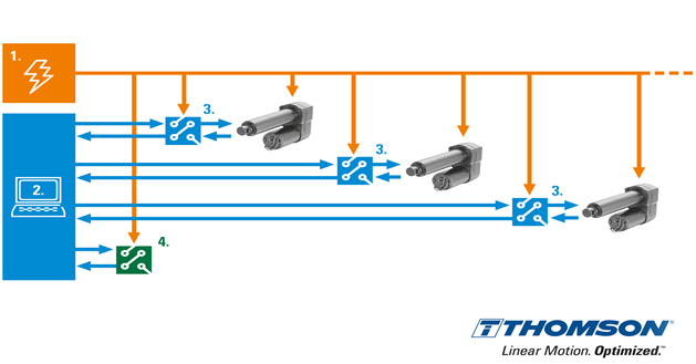
Fig. 1 – System without CAN bus
However, by utilizing smart actuators that are compatible with the J1939 CAN bus standard, multiple actuators can be operated on a network via one main ECU. This opens previously unavailable opportunities for more complex control strategies. It also adds considerable flexibility, in that the same actuator can be used in different applications.
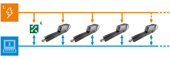
Fig. 2 – System with CAN bus
There are also significant savings in engineering time and cost, as well as a dramatic reduction in wiring. Where previously deploying an actuator to an ECU required a dedicated communications cable to that ECU, a thick power cable to the equipment battery, and a relay or switch. An actuator with onboard compatibility simply connects to the J1939 bus, allowing more efficient connections to the power supply.
Putting J1939-enabled actuators to work
As long as there is a J1939 CAN bus network, which is increasingly becoming the norm, OEMs can incorporate electric actuators into their designs easily and at a fraction of the expense that might have been necessary otherwise. They also eliminate the need for independent controllers, utilizing the same actuator for multiple applications while having access to remote diagnostics.
Eliminating the standalone controller
Traditional electric actuators are operated by a stand-alone ECU. By using actuators with integrated J1939 support, however, only a single cable needs to run from the controller to all actuators. Each actuator has a unique address, listens to every signal from the vehicle control system and responds only to signals designated for its operation. These smart actuators also provide basic diagnostics that alert the control unit of its speed and position, enabling a greater level of automation.
Same actuator, different applications
A farm equipment manufacturer may strive to utilize one actuator design for several applications. For example, one application may require a 2000-pound push/pull force for six inches of travel, while another may only require 500 pounds for four inches of travel. While traditionally, this would require a completely different actuator design for each application, a J1939-compatible actuator allows a systems engineer to program identical units to function specifically to the application requirements, saving engineering time, wiring, and the cost of adding and maintaining a separate controller. By electronically modifying the stroke length, for example, they use the same-size actuator and housing for one application with a 500-pound trip point and another with a 2000-pound trip point. Using one common actuator for multiple applications not only allows for easier diagnostics (error monitoring a single actuator design is easier than monitoring 4 different types, for example), but also simplifies ordering and inventory. The use of a single actuator also improves lead time, as it is easier fit it into a design, meaning reduced installation time and lower system cost.
Remote diagnostics
Condition monitoring, new motion control capabilities and J1939 support work together to provide OEMs and end-users with powerful diagnostic capabilities. For example, an engineer in Iowa might be able to remotely dial into a combine in North Dakota to determine the cause of failure on a particular actuator. The failure would be indicated by an electronic message flag, which is used to help reveal the cause of the failure. Some examples of message flags include temperature, position, current and input voltage.
New alternative for heavy duty applications
New onboard electronics capabilities, combined with the stroke and load increase, higher power and heightened protection from harsh environmental conditions, make electromechanical actuators more viable for even the most demanding outdoor applications. Electromechanical actuators deliver comparable, or even superior, performance, are cleaner, easier to operate, and have lower total cost of ownership and operation than their predecessors.
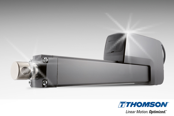
Title Image: The new Electrak HD? electric linear actuator from Thomson Industries offers industry-leading, onboard electronics with built-in J1939 CAN bus option that enhances controllability, can eliminate individual controls and simplifies OEM machine design.